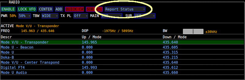
SDR/DL Button
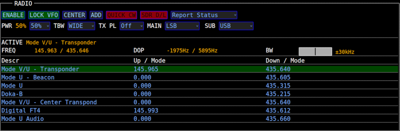
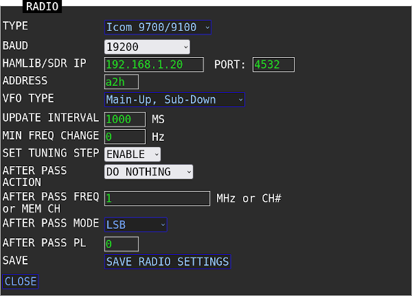
When using an SDR, a new button will appear in the radio section of the S.A.T.
SDR D/L
This button lets the S.A.T. know which receiver is controlling the downlink frequency. Normally, without an SDR, you tune your radio with the VFO knob and the S.A.T. will adjust accordingly. If you enable this button while using an SDR, you can tune with the SDR program and the S.A.T. will adjust accordingly with the new SDR frequency instead of the radio.
To disable SDR support in the S.A.T. you only need to set the port to zero. The IP address can be left in the box. The S.A.T. will not try to connect to a SDR program if the port is zero.
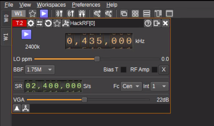
SDR Angel Setup
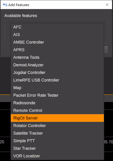
Click the Add Feature button  to open the Add Feature dialog. Select RigCtl Server and click the Apply button. Click Close to close the Add Feature dialog. to open the Add Feature dialog. Select RigCtl Server and click the Apply button. Click Close to close the Add Feature dialog.
The RigCtl Server window should be displayed:
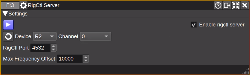
Select your device and channel in the RigCtl settings. You must already have a channel active in order to use RigCtl. It doesn't matter what mode of channel you select since the S.A.T. will send the command to change it.
Click the blue Play button to start the RigCtl Server.
SDR Angel should now respond to frequency and mode commands sent by the S.A.T.
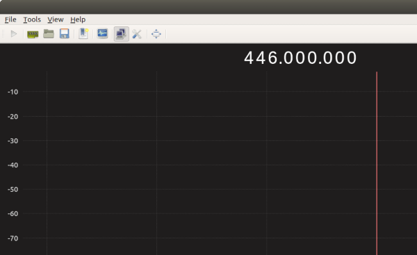
Gqrx Setup
To configure Gqrx you will need to add the IP address of the S.A.T. into the network setting panel.
In the Tools Menu - click Remote control settings to open the network setting panel:
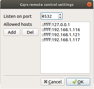
Click the Button to add a new entry in the list on the right. Here you will enter the IP address of the S.A.T.
The IP address must be entered in a very specific way. For example, if the IP address of your S.A.T. is 192.168.1.123 it must be entered list this:
::ffff:192.168.1.123
We recommend using 4532 for the port number since it is the customary one used for Hamlib radio control. However, you can choose any port you like so long as it matches the port number set in the S.A.T.
Ensure that port you have selected is not blocked by your computers firewall. You may need to add an exception for it.
Click OK to save the settings.
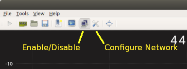
Once the settings are saved, you enable remote control in the Tools Menu and selecting Remote control
Gqrx should now respond to frequency and mode commands sent by the S.A.T.
You can quickly enable and disable the network control in Gqrx by using the buttons instead of the menu:
UDP Broadcasts
The S.A.T. will broadcast a UDP packet on port 9932 when certain events occur.
The data format is a comma seperate string each of which is described below. All packets starts with the text "SAT" and the name of the event. Each packet ends with a newline character (\n).
| BOOT |
Broadcast when the S.A.T. is power up.
Format: SAT,BOOT,SERIAL,VERSION
- SERIAL is the serial number of the S.A.T.
- VERSION is the firmware version.
Example: SAT,BOOT,1147717711,8.600
|
| START TRACK |
Broadcast when the S.A.T. starts to track a satellite.
Format: SAT,START TRACK,NAME,CATNO
- NAME is the tracked satellite name.
- CATNO is the tracked satellite catalog number.
Example: SAT,START TRACK,LEDSAT,49069
|
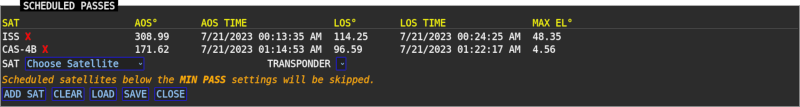
| AOS |
Broadcast when the tracked satellite reaches AOS
Format: SAT,AOS,AZ
- AZ is the azimuth of the satellite at AOS.
Example: SAT,AOS,27.1
|
| LOS |
Broadcast when the tracked satellite reaches LOS
Format: SAT,LOS,AZ
- AZ is the azimuth of the satellite at LOS.
Example: SAT,LOS,174.9
|
| TRANSPONDER |
Broadcast when a transponder is selected.
Format: SAT,TRANSPONDER,NAME,UPFREQ,UPMODE,DOWNFREQ,DOWNMODE
- NAME is the transponder name.
- UPFREQ is the uplink frequency in Hz.
- UPMODE is the uplink mode.
- DOWNFREQ is the downlink frequency in Hz.
- DOWNMODE is the uplink mode.
Example: SAT,TRANSPONDER,1200 Baud Data,435310000,USB-D,435190000,USB-D
|
| STOP |
Broadcast when a S.A.T. stops tracking a satellite.
Format: SAT,STOP
Example: SAT,STOP
|
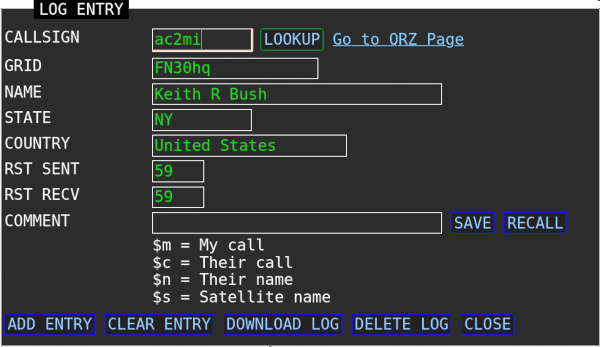
| QSO |
Broadcast when a QSO log entry is added
Format: SAT,TRANSPONDER,SATNAME,CALL,GRID,MODE,COMMENT,RSTSENT,RSTRECV,UPFREQ,DOWNFREQ,NAME
- SATNAME is the satellite name.
- CALL is the contact callsign.
- GRID is the contact grid.
- MODE is the contact mode.
- COMMENT is the QSO log comment.
- RSTSENT is the RST sent.
- RSTRECV is the RST received.
- UPFREQ is the uplink frequency in Hz.
- DOWNFREQ is the downlink frequency in Hz.
- NAME is the contact name.
Example: SAT,QSO,LEDSAT,KC2SYF,fn30ha,PKT,Thanks!,59,59,435.311036,435.188964,Mike
|
FAQ
Common Questions / Troubleshooting
The S.A.T. is much slower than normal.
The S.A.T. is having trouble communicating with your radio. Check all connections and radio settings (address & baud). If you do not have a radio attached ensure that the radio type is set to NONE in the radio settings panel.
How do I connect to a hidden WiFi network?
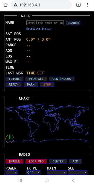
First connect to the Access Point of S.A.T. as described above. Once connected enter the following into the browser address bar:
http://192.168.4.1/?a=W|APNAME|password
Replace APNAME with the exact name of the hidden WiFi network and "password" with the password for the network.
Once entered, your S.A.T. will reboot and should connect to the hidden WiFi network.
If there are spaces or punctuation in the SSID or password then it must be URL encoded first. Click here for an online encoding calculator.
Example:
The hidden network name is My Hidden_Network! and the password is My#$%Password.
The SSID gets encoded to My+Hidden_Network%21
The password gets encoded to My%23%24%25Password
The complete URL encoded string would then be:
http://192.168.4.1/?a=W|My+Hidden_Network%21|My%23%24%25Password
What's in the box?
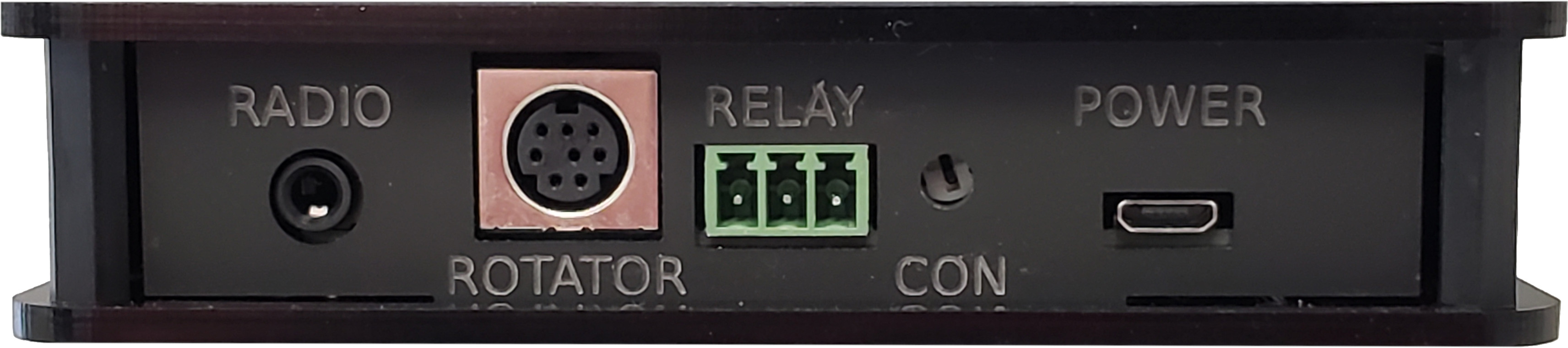
You should receive the S.A.T. device along with Micro-USB power cable, Rotator DIN cable, and a TRS cable to interface with Icom radios. A Micro-USB power adapter is not included.
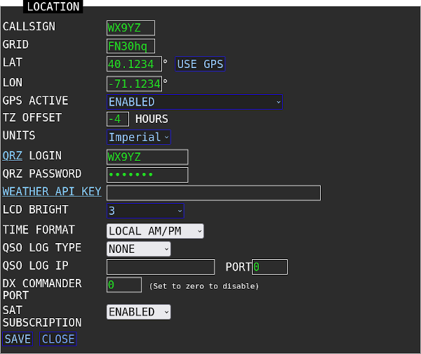
How is the clock set?
The clock on the S.A.T. is set automatically by the web browser that opens the S.A.T. dashboard. You can choose from various time display settings in the LOCATION panel.
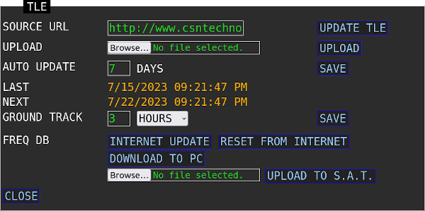
I get an error when I download TLEs
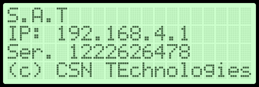
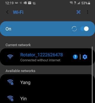
First make sure that the S.A.T. is not in access point mode and is connected to a WiFi network that has internet access. When in access point mode the IP address on the LCD will be 192.168.4.1 and there will be a WiFi network available on your mobile device with the name 'CSN_SAT_XXXX' where XXXX is the SAT serial number.
The S.A.T. does not support http s addresses for the TLE url (note the 's' at the end of 'http'). Usually you can simply remove the 's' from the address and try again. If it still doesn't work, and you need to have that list, you'll have to download it to your device. Then you can upload it using the "Custom TLE Files" procedure described above.
The following TLE sources and know to work well:
AMSAT nasabare.txt (updated weekly)
http://www.amsat.org/tle/current/nasabare.txt
CSN nasabare.txt (a copy of AMSATs nasabare.txt) -
http://www.csntechnologies.net/SAT/nasabare.txt
CSN csnbare.txt (same satellites as nasabare.txt but generated with Celestrack data, updated daily) -
http://www.csntechnologies.net/SAT/csnbare.txt
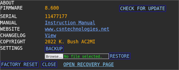
How do I factory reset?
You can find the Factory Reset button in the About box in the web interface.
Another way to factory reset is remove power from the SAT and short the CI-V cable contacts with aluminum foil. When the SAT is powered up with the cable shorted it will enter reset mode. You will then have two opportunities to release the short, depending of what type of reset you want. Watch the SAT's LCD and after a few seconds it will tell that if you release the short it will reset the WiFi. If you keep holding the short it will then tell you if you release that it do a full factory reset. When finished it will ask you to reboot the SAT which you can do by removing the USB power plug, waiting a couple of seconds, then reinsert it.
QRZ Lookups Are Not Working
Various web browser plugings may be preventing the S.A.T. from accessing the QRZ.com. Try disabling these plugins or adding exceptions if possible.
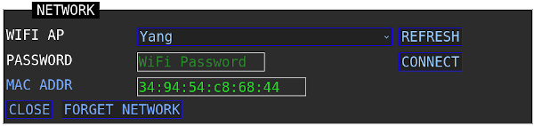
I cant connect the S.A.T. to my WiFi network!
The S.A.T. can only connect to 2.4Ghz networks. The S.A.T. searches for available access points when NETWORK panel is opened and also when the REFRESH button is clicked. Allow a few seconds for the search to complete. The discovered networks are then displayed in the WIFI AP selection box.
Not being able to connect is usually caused by not having the correct WiFi password. Check the 2.4G password in your router settings, sometimes it is not the same as the 5G one.
We found that there is a setting in xFinity access points that can prevent it from connecting. Find and uncheck the 'Prefer private Connections' setting in your routers configuration.
Also make sure that your access point if not filtering by MAC address for new connections.
Ubiquity networks - If you have slow performance or difficuly connecting you may need to enable Legacy Wireless Mode. Please consult your devices documentation for more information.
Starlink Wifi - Try seperating the 5G and 2.4G networks in you Starlink settings.
|